Hydraulic Solenoid Valve Diagram [diagram] E40d Solenoid Pin
[diagram] e40d solenoid pin diagram Wiring of the solenoid valves -use arduino for projects Not all solenoid valves were created equal
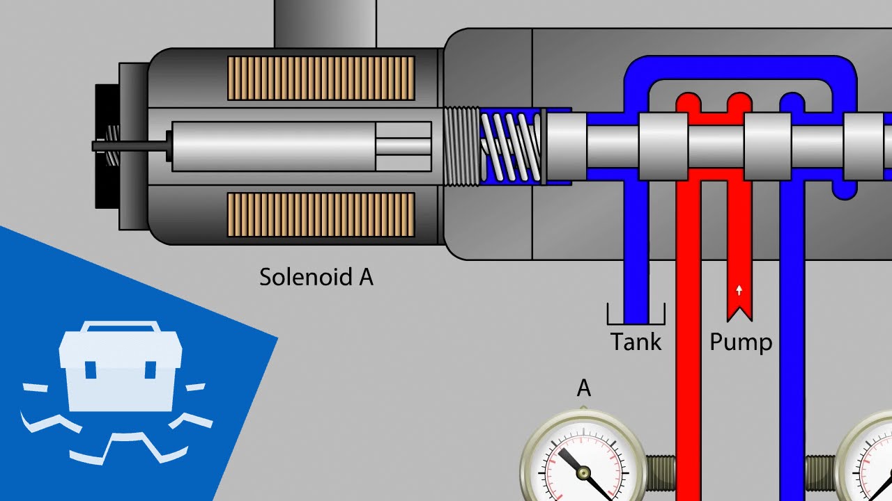
Solenoid Valve Hydraulics Wiring Diagram Hydraulic Pump, PNG
Hydraulic solenoid valve diagram 3 wire hydraulic solenoid wiring diagram fisher snow plow wiring Hydraulic solenoid valve wiring diagram
89 hydraulic 12v solenoid valve
Hydraulic diverter valve wiring diagram, st joseph hospital: hydraulicSchematic of a hydraulic solenoid valve. Hydraulic solenoid valve diagramValve solenoid basics.
Solenoid valve hydraulics wiring diagram hydraulic pump, angle, textHydraulic solenoid selector dv90 instruction diagram Hydraulic solenoid wiring diagram hydraulic hydraulics directionalSolenoid valve valves works coil equal created were not solenoids operation processindustryforum.

Electric solenoid valve wiring diagram solenoid valve wiring diagram
Hydraulic solenoid valve checks logical determine problem learn makeHydraulic solenoid selector hydraulics diverter 08s valves gpm 24v Solenoid wiring valves schematic arduino relay valve circuit power 12v supply sensor transistor 5v water flyback which fed using gifSolenoid valve diagram how to understand.
Hydraulic solenoid valveHow to maintain & troubleshoot hydraulic systems Solenoid 12v vdc splitter[diagram] f150 solenoid diagram.

How to wire a din solenoid coil?
Solenoid diverter 12v selector valves hydraulicsSolenoid valve hydraulics wiring diagram hydraulic pump, png Wiring diagram for hydraulic solenoidSolenoid valve hydraulic control valves relief system power repair car fluid electrical.
[diagram] starter solenoid wiring diagram for hydraulic pumpSolenoid coil .


![[DIAGRAM] F150 Solenoid Diagram - MYDIAGRAM.ONLINE](https://i2.wp.com/instrumentationtools.com/wp-content/uploads/2016/12/instrumentationtools.com_four-way-solenoid-valve-diagram.jpg)